I've been trying to do some RF experiments, but instead being driven mad by hand-wound coils that never seem to behave as the standard coil inductance calculations would lead us to believe.
As always, it's w2aew to the rescue with a neat deconstruction and demo of a circuit for coil or inductor measurement.
I built the circuit out, and was easily measuring down to 10µH on a breadboard, and sub-1µH once I put the circuit on a hacked up copper board with islands. Using the LC circuit resonant frequency formula, it's possible to work backwards from known frequency and capacitance to determine the inductance (wolframalpha is great for this).
So now I hope to get back into some RF without the nagging doubt of not really knowing what my coils are doing!
As always, all notes, schematics and code are in the Little Arduino Projects repo on GitHub.
Here's a beautiful trace of a (nominally) 10µH choke with a 150pF capacitor. I measure the frequency at 4.26MHz, therefore an actual inductance of 9.3µH .. pretty close!
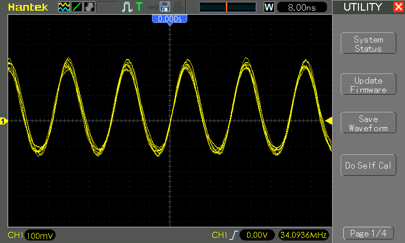
Even with a super-bodgy 4.5 turn coil whipped up on the spot and put in parallel with a 30pF capacitor, I'm still getting a decent oscillation at 34.09MHz for a calculated inductance of 0.73µH
And here's the board delivering the results:


No comments:
Post a Comment