


The Basílica i Temple Expiatori de la Sagrada Família has been under construction since 1882. The magnitude of the vision driving the project - both physically and creatively - is striking, especially at first hand.
Then you see the work in progress - the cranes, scaffolding, workers scurrying around the site. But that is what I think really brings it to life. This is not a frozen, finished statement of something other-worldy. It's a vibrant expression of the hope and aspirations of a whole bunch of people working together.
In other words, it is the ultimate maker project! Personally, I think it will be a sad day when someone declares it actually "finished".
Now at the extreme other end of the maker-scale is this neat little paper nano Sagrada Familia kit that I picked up in my travels.
I've "electrified" it to some extent with some LowVoltageGlowingLEDs that animate the background, just running off a 1.5V supply. Although I think I could have slowed down the LEDs even further.
A nice effect I think..
As always, all notes, schematics and code are in the Little Arduino Projects repo on GitHub.
Monday, February 29, 2016
Sunday, February 28, 2016
LittleArduinoProjects#191 glowing LEDs on 1.5V
So for another project I wanted some "glowing" LEDs, ideally powered from a single 1.5V AA or AAA battery. That seemed like an interesting challenge, especially when the forward voltage of the LEDs I'm using is about 2.1V.
I had a feeling I could cobble together a couple of ideas (Relaxation Joule Thief and RC Oscillator) .. and lo, it works!
As always, all notes, schematics and code are in the Little Arduino Projects repo on GitHub.
Here's a glimpse of the "modified oscillation". CH2 (red) is the LED cathode/transistor collector - as it rises and falls the LED slowly switches off then back on.
For protoboard-based builds I tend to layout the schematic with PAD tools (Pencil-Aided Design) ...
Thursday, February 25, 2016
LittleArduinoProjects#137 Toroidal Joule Thief
In #129 I posted about a two-transistor boost circuit. This is an even simpler circuit - very common over around the internet and known as the archetypal "joule thief". The smallest I've seen is Eric Wasatonic's micro version.
I stuffed my circuit into a AA battery holder and it works great as a night light, powered by either a single somewhat-depleted AA or AAA battery.
As always, all notes, schematics and code are in the Little Arduino Projects repo on GitHub.

I stuffed my circuit into a AA battery holder and it works great as a night light, powered by either a single somewhat-depleted AA or AAA battery.
As always, all notes, schematics and code are in the Little Arduino Projects repo on GitHub.
Wednesday, February 24, 2016
LittleArduinoProjects#129 Relaxation Joule Thief
I was inspired by w2aew's excellent video to check out the Ears To Our World humanlight project. It's a good cause, although shipping costs kill the idea of buying one myself - better just to make a direct donation.
It's also an interesting circuit - a variation on the many "joule thief" circuits out there - and also demonstrates some of the basics that under-pin boost converter power supplies.
As always, all notes, schematics and code are in the Little Arduino Projects repo on GitHub.

With my particular mix of components, I'm getting almost 40% duty cycle which actually produces an apparently very bright LED on just 1.5V supply.

It's also an interesting circuit - a variation on the many "joule thief" circuits out there - and also demonstrates some of the basics that under-pin boost converter power supplies.
As always, all notes, schematics and code are in the Little Arduino Projects repo on GitHub.
With my particular mix of components, I'm getting almost 40% duty cycle which actually produces an apparently very bright LED on just 1.5V supply.
Monday, February 22, 2016
LittleArduinoProjects#001 basics of 7-segment LED control
Going back to basics - this project is a test of directly driving a common cathode 7-segment LED with an Arduino. It covers the fundamentals behind more advanced circuits like this custom PCB with register interface.
As always, all notes, schematics and code are in the Little Arduino Projects repo on GitHub.

As always, all notes, schematics and code are in the Little Arduino Projects repo on GitHub.
Saturday, February 20, 2016
LittleArduinoProjects#178 making a 7-segment LED PCB
My version of the second project from the KiCad like a Pro course (the first was an nRF24 breakout board).
The board combines a common-cathode 7-segment display with a shift register and current-limiting resistors. Nothing earth-shattering, but a good little KiCad exercise. I recently got the boards back from OSH Park, and they work just fine!
As always, all notes, schematics and code (including the KiCad project) are in the Little Arduino Projects repo on GitHub.
LittleArduinoProjects#188 read/write AT24C02 external EEPROM
The AT24C02 is from Atmel's line of serial EEPROM chips with a whopping capacity of 2K! (256 x 8) That's not a whole lot more than the onboard EEPROM in an Arduino, but it does have the advantage of being external:
As always, all notes, schematics and code are in the Little Arduino Projects repo on GitHub.
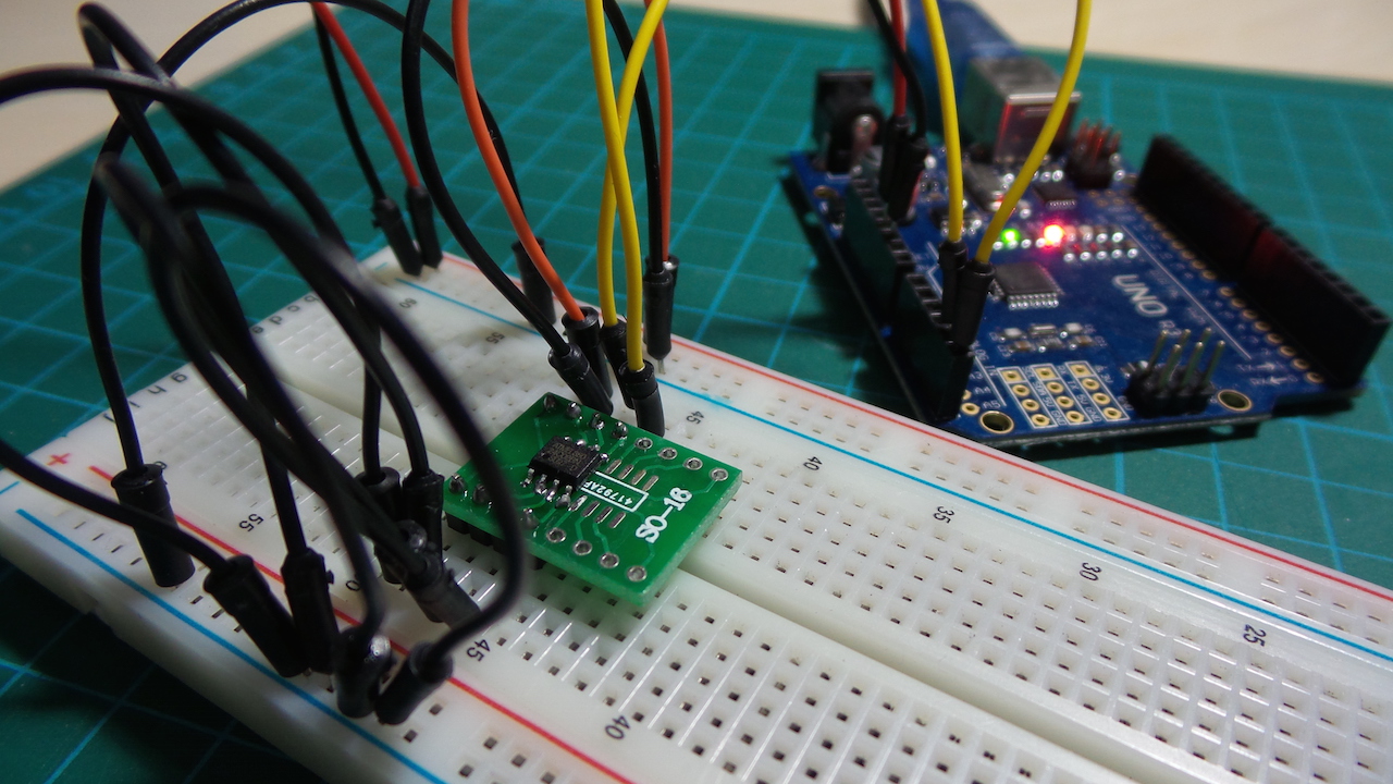
- it can stay in-situ even if the microcontroller disappears/gets exchanged
- multiple devices can share access
As always, all notes, schematics and code are in the Little Arduino Projects repo on GitHub.
Friday, February 19, 2016
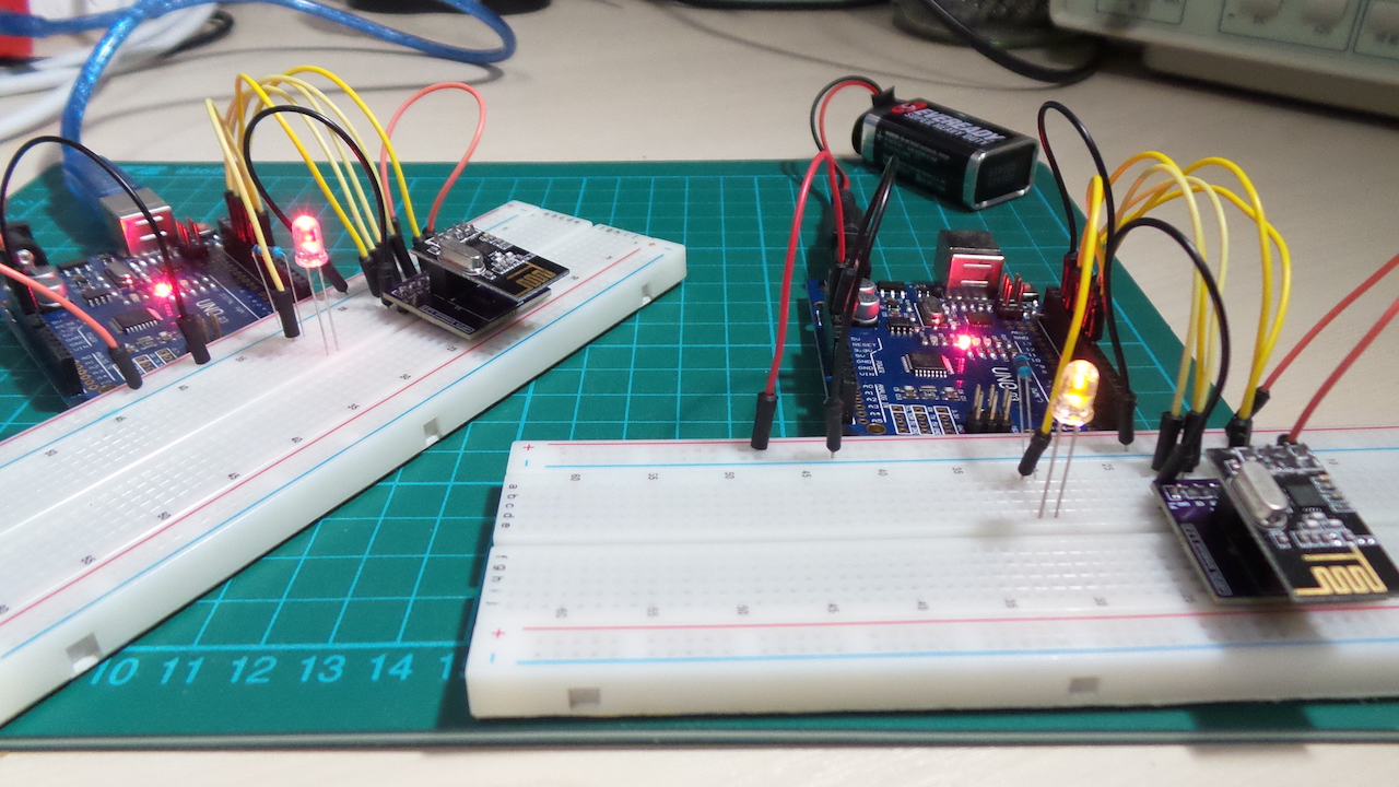
LittleArduinoProjects#187 nRF24L01+ Ping Pong
So now I have my nRF24 breakout boards back from OSH Park, time to try them out.
This is a simple script that runs on two Arduinos. They bounce messages back and forth over 2.4GHz using the nRF24L01+ modules, flashing their LEDs when messages successfully handled. Sweet, and the breakout boards work just fine.
As always, all notes, schematics and code are in the Little Arduino Projects repo on GitHub.
Wednesday, February 17, 2016
LittleArduinoProjects#176 nRF24 Breakout Board
So recently I've been intrigued by small-batch PCB fab services, like OSH Park. Like the ready supply of components from various online sellers, it's amazing how cheap you can get boards made over the net these days. How do they do it? As I learned in this hardware hangout, there are some neat tricks done behind the scenes to aggregate small orders into full panels sent to a fab.
But to get PCBs made, you need to be able to drive an EDA tool like KiCad. KiCad's a beautiful open source tool, but it is quite idiosyncratic. In some spare time, I dived into the KiCad like a Pro course and found it an excellent leg-up on the process.
The nRF24 breakout board (below) is just the first trivial exercise from the course. But it will come in handy - I have a batch of nRF24's lying around that I've been planning to experiment with, and the breakout board will be quite handy for that.
I just received my boards from OSH Park (1 month from order to delivery in Singapore - not bad, especially for $4.80 all-in). Very impressed with the board quality. Not so much with the board design! A few things I can see could be easily improved, but that's my fault (see my notes). But they do work!
As always, all notes, schematics and code (including the KiCad project) are in the Little Arduino Projects repo on GitHub.
Sunday, February 14, 2016
LittleArduinoProjects#186 Asynchronous Counters with JK Flip-Flops
A quick demonstration using four JK flip-flops set up in "toggle" mode to implement an asynchronous 4-bit binary counter. This is the classic circuit, straight out of a text book. It's implemented with:

Why "asynchronous"? This refers to the fact that the output of each flip-flip cascades to trigger the next in series. Although instantaneous to the eye, there is none-the-less a propagation delay as the changes ripple through the flip flops. It's clearly seen in an analog scope trace. Here is the falling edge of 0xF transitioning to 0x0, which ripples over about a 42ns period:

Here's a quick video of the circuit in action ... though definitely not the most exciting thing you'll see on YouTube today:
- two 74LS73 for the flip-flops
- a 555 Timer astable oscillator providing the clock pulse
Why "asynchronous"? This refers to the fact that the output of each flip-flip cascades to trigger the next in series. Although instantaneous to the eye, there is none-the-less a propagation delay as the changes ripple through the flip flops. It's clearly seen in an analog scope trace. Here is the falling edge of 0xF transitioning to 0x0, which ripples over about a 42ns period:
Here's a quick video of the circuit in action ... though definitely not the most exciting thing you'll see on YouTube today:
Saturday, February 13, 2016
LittleArduinoProjects#185 Building the Böhm Stirling-Technik HB13 Small Bonsai
What has this to do with electronics? Well, nothing (yet), but there's ample scope later;-)
A Stirling engine is a closed-cycle regenerative heat engine with a permanently gaseous working fluid. They are named after Robert Stirling who invented the first practical example in 1816.
Böhm is a small(?) specialist manufacturer from Germany that's taken up a side-line in producing Stirling engine kits. When I first discovered them, I couldn't resist. So here's my build of the Small Bonsai (HB-13).
As always, all my notes and schematics are in the Little Arduino Projects repo on GitHub.
LittleArduinoProjects#184 Adjustable Pulse Generator
Yet another variation on the basic 555 timer astable oscillator to allow a wide range of frequency and duty cycle adjustments. It's similar to the circuit used in kits like this.
As you can see from the schematic, it's the combination of pot and capacitor selector that produce the wide range of oscillator control:

But the challenge with the classic 555 astable circuit is trying to hold frequency or duty cycle constant while adjusting the other. This circuit doesn't solve that problem, but for something different, I plotted the functions with WolframAlpha. If you correlate the two graphs below, you can see the severe penalty you pay in terms of duty cycle when attempting to push for maximum frequency. It definitely is a case of trying to find the best compromise for your application.
As always, all notes, schematics and code are in the Little Arduino Projects repo on GitHub, including live links to WolframAlpha to reproduce these plots.


As you can see from the schematic, it's the combination of pot and capacitor selector that produce the wide range of oscillator control:
But the challenge with the classic 555 astable circuit is trying to hold frequency or duty cycle constant while adjusting the other. This circuit doesn't solve that problem, but for something different, I plotted the functions with WolframAlpha. If you correlate the two graphs below, you can see the severe penalty you pay in terms of duty cycle when attempting to push for maximum frequency. It definitely is a case of trying to find the best compromise for your application.
As always, all notes, schematics and code are in the Little Arduino Projects repo on GitHub, including live links to WolframAlpha to reproduce these plots.
Frequency for all values of R1, R2 (C=1µF)
Duty Cycle for all values of R1, R2 (C=1µF)
Thursday, February 11, 2016
LittleArduinoProjects#183 Polarity Testing
A simple polarity test for uses a series of inverters. The input signal is pumped into two parallel inverter chains:
I used a venerable CD4069 for a quick test, although any inverter (matched to the voltage of the signal) will do. The result of the polarity test is displayed with a pair of LEDs reversed in parallel.
As always, all notes, schematics and code are in the Little Arduino Projects repo on GitHub.
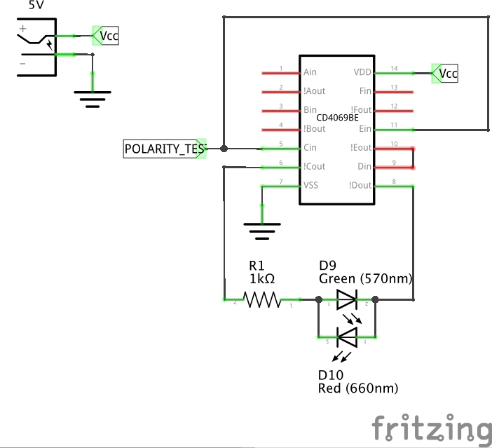
- a single inverter
- a series of two inverters
I used a venerable CD4069 for a quick test, although any inverter (matched to the voltage of the signal) will do. The result of the polarity test is displayed with a pair of LEDs reversed in parallel.
As always, all notes, schematics and code are in the Little Arduino Projects repo on GitHub.
Wednesday, February 10, 2016
LittleArduinoProjects#182 Building a Bench Power Supply
I've wanted a variable mains-powered power supply for a while, so when I found this kit for a reasonable price I decided to give it a go. Some things that attracted me:
The kit and PCB comes with a few "valued-added features" unrelated to the power supply function (CD4069 square-wave generator, externally-triggered piezo buzzer, externally-triggered polarity tester), but I decided to leave those out of the build.
I also enjoyed investigating and old-school transformer-based power supply. These are getting rare .. it's hard to even find a 220/12 transformer for less than the price of the kit these days, and then they are mostly used/refurbished.
How does it perform? Nice! No smoke on power-up, but a few things to note and/or improve. And I'm sure it wouldn't pass a safety certification, so don't go building one like this for friends.
As always, all notes, schematics and code are in the Little Arduino Projects repo on GitHub.

- 220V/110V mains-powered
- continuously adjustable output voltage
- isolated output
- nice acrylic case
- built-in LED voltmeter
The kit and PCB comes with a few "valued-added features" unrelated to the power supply function (CD4069 square-wave generator, externally-triggered piezo buzzer, externally-triggered polarity tester), but I decided to leave those out of the build.
I also enjoyed investigating and old-school transformer-based power supply. These are getting rare .. it's hard to even find a 220/12 transformer for less than the price of the kit these days, and then they are mostly used/refurbished.
How does it perform? Nice! No smoke on power-up, but a few things to note and/or improve. And I'm sure it wouldn't pass a safety certification, so don't go building one like this for friends.
As always, all notes, schematics and code are in the Little Arduino Projects repo on GitHub.
LittleArduinoProjects#181 Voltmeter Modules
Voltmeter modules are a very convenient way of adding voltage display to any project, because they require no supporting circuitry or microcontrollers.
There are two and three wire modules in the market. Two-wire modules are the simplest (and generally cheapest). For most applications where a simple readout of a power supply is required, they are most convenient since a separate power supply connection is not required. It does mean of course that the meter draws current from the circuit under test, and will only work down to a certain voltage (usually ~4.5V).
For more precision measurement, the three-wire modules are best as they present relatively high input impedance (> 100kΩ), and can measure voltages all the way down to 0. As an example, Adafruit have this 3-wire module in their catalogue, but they are widely available from most online sellers.
I recently received a 3-wire module as part of a kit and put it to the test. Using my DMM as a reference, it appears accuracy is within 40mV, good enough for general purposes.
As always, all notes, schematics and code are in the Little Arduino Projects repo on GitHub.
Tuesday, February 09, 2016
LittleArduinoProjects#180 Colpitts Oscillator
A Colpitts oscillator uses a combination of inductors and capacitors to produce an oscillation at the resonant frequency of LC circuit.
To see that in action, I built one on a protoboard and it delivers an almost perfect 22.9kHz .. compared to the theoretical 22.5kHz.
As always, all notes, schematics and code are in the Little Arduino Projects repo on GitHub.
Here's a trace of the output signal on CH1, and the mid-point of the capacitor pair on CH2:
Monday, February 08, 2016
LittleArduinoProjects#174 USB LED Notifiers
So four of these USB Webmail Notifier devices turned up in a dusty cupboard
in the office.
A quick tear-down shows they contain a super-simple circuit - just a
SONiX Technology SN8P2203SB 8-Bit microcontroller that handles the USB protocol and drives an RGB LED. The SN8P2203SB is an old chip phased out 2010/04/30, superseded by the SN8P2240. They have a supremely primitive USB implementation - basically mimicking a very basic USB 1.0 HID device.
A quick google reveals quite a bit of old code lying around for various projects using devices like this. Most seem to use libusb for convenience - and often 0.1 legacy libusb that. As I'm mainly on MacOSX, the code is not much use since Apple no longer allows claiming of HID devices
and the libusb team decided not to try to get around that.
So to bring things up-to-date, I wrote a simple demo using hidapi
and things all work fine - see the video below.
Now I just need to ponder on good ideas for what to do with these things!
As always, all all notes, schematics and code are in the Little Arduino Projects repo on GitHub.
Sunday, February 07, 2016
LittleArduinoProjects#173 Mini 64-LED Cube
LED cubes were a "thing" a few years back maybe ... but I've never built one. Time to fix that...
Here's my "mini" 4x4x4 cube - 3cm per side with 3mm clear blue LEDs. Pretty compact, and delivers nice effects. The clear blue LEDs work really well - very bright, even when driven with minimal current.
It's encased in a Ferrero Rocher cube box. During the build, that raised some challenges - most of the effort in building the project concerned squeezing all the electronics into the space in the lid (which becomes the base of the cube). Not quite as small as HariFun's "World's Tiniest RGB LED Cube" but about as small as you can get without resorting to SMD LEDs!
As always, all notes, schematics and code are in the Little Arduino Projects repo on GitHub. Here's a quick demo:
Subscribe to:
Posts (Atom)